
Heavy duty CNC lathes stand out when the workpieces grow large, the cuts dig deep, and the demands for accuracy stay high. These machines handle big shafts, thick tubes, and massive flanges that ordinary lathes cannot manage. Operators load a rough casting or forging, program the path, and watch the tool remove metal in controlled passes until the part matches the drawing.
The machines combine rigid frames, powerful spindles, and computer control so that each cut stays consistent from the first piece to the hundredth. This reliability makes them central in plants that produce components for energy, transport, and heavy equipment.
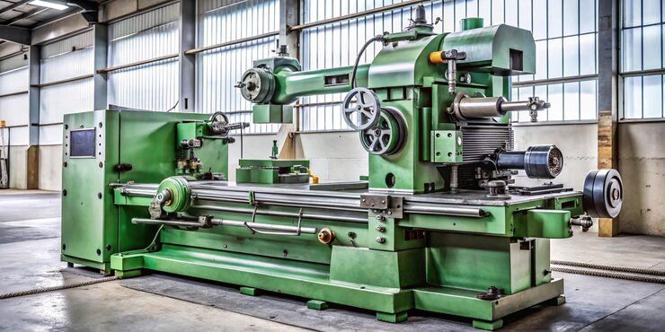
What Sets a Heavy Duty CNC Lathe Apart
A heavy duty model starts with a bed that resists twisting under heavy cutting forces. The ways are wider and the structure thicker than on lighter machines. Spindles deliver higher torque at lower speeds so the tool can take deep cuts in tough alloys without stalling.
Chuck sizes often exceed 500 mm, and the distance between centers can stretch several meters. These dimensions let the machine turn long propeller shafts or large valve bodies in one setup. The CNC system stores tool offsets, compensates for thermal growth, and keeps the surface finish within tight limits even after hours of continuous cutting.
Key Structural Features
- Extra-wide bed and saddle for stability
- High-torque spindle motors with gearboxes
- Large-capacity tool turrets or tool posts
- Strong tailstocks and steady rests for long parts
These elements work together so vibration stays low and accuracy remains high.
Main Machine Types in Daily Use
Workshops choose different layouts according to the shape and size of the parts they produce.
Horizontal Heavy Duty Lathes
The spindle sits parallel to the floor. Long bars and shafts rest between the chuck and the tailstock. This layout suits pipelines, hydraulic cylinders, and rotor shafts. The operator can reach the work area easily and change tools without climbing.
Vertical Turret Lathes
The spindle points upward. Heavy discs and rings sit on a faceplate and spin like a potter’s wheel. Gravity helps hold the part in place, which reduces the need for complex fixturing. These machines handle large gear blanks, turbine discs, and bearing housings.
Multi-Axis Turning Centers
Extra axes allow milling, drilling, and turning in the same setup. Live tools spin in the turret so the machine can cut keyways or bolt holes without moving the part to another station. Complex shapes emerge faster and with better alignment.
Twin-Spindle Configurations
Two spindles work in sequence. One side finishes the first end of the part while the other side prepares the opposite end. Cycle times drop and the finished piece leaves the machine complete.
CNC Turning Technologies That Drive Precision
Modern controls read G-code or conversational programs and translate them into precise motion. Servo motors move the slides along the X and Z axes while the spindle rotates at the commanded speed.
Tool life management tracks how many minutes each insert has cut. When the limit approaches, the system signals a change. Adaptive control senses rising cutting forces and slows the feed to protect the tool and the machine.
Coolant systems deliver high-pressure fluid through the tool tip. The stream clears chips from deep bores and keeps the cutting edge cool. Some setups use minimum-quantity lubrication to reduce fluid use while still protecting the surface.
Threading cycles produce precise pitch over long lengths. The control synchronizes the spindle rotation with the Z-axis travel so the tool follows an exact helix. Operators dial in the pitch, depth, and number of passes, then let the machine complete the thread.
Manufacturing Processes from Raw Stock to Finished Part
The sequence begins with material preparation. Bars or billets arrive cut to rough length. The operator loads the piece into the chuck, indicates it for concentricity, and clamps it firmly.
Facing cleans the end surface. Rough turning removes the bulk of the excess material in deep cuts. Finishing passes leave the final diameter and surface texture. Boring opens internal diameters to size. Grooving and parting separate features or cut the part to length.
When live tooling is available, the same program drills radial holes or mills flats. Steady rests support slender shafts so they do not deflect under the cutting force. After the last pass, the machine stops, the operator measures critical dimensions, and the part moves to the next station or to inspection.
For large batches the program stores offsets for each tool. A probe can check the part still in the machine and update those offsets automatically. The result is consistent quality across hundreds of pieces.
Global Centers That Produce These Machines
Factories in several regions specialize in heavy duty designs. German and Italian builders focus on high-precision frames and advanced control packages. Japanese makers emphasize reliability and long-term accuracy under continuous load. Chinese plants supply a wide range of capacities that match mid-volume production needs. American facilities often customize machines for specific industries such as oil-field equipment or large electric motors.
Each region brings its own strengths in casting quality, drive technology, and software integration. Buyers look at local support networks, spare-part availability, and the ability of the builder to adapt the machine to particular workpiece sizes.
Industrial Applications Across Key Sectors
Energy plants rely on these lathes for turbine shafts, generator rotors, and large valve bodies. The machines turn the massive diameters and hold the tight runout needed for high-speed rotation.
Shipbuilding yards use them for propeller shafts and intermediate shafts that can exceed ten meters in length. Steady rests and follow rests keep the long workpieces from whipping.
Heavy equipment makers turn axles, hydraulic cylinders, and final-drive components. The high torque capacity lets the tool cut through tough steels without multiple setups.
Aerospace and defense shops machine landing-gear struts and engine casings from high-strength alloys. Multi-axis versions finish complex contours in fewer operations.
Mining and construction equipment producers rely on the same machines for large bushings, pins, and drum shafts. The rigid structure absorbs the interrupted cuts that come with hard-facing layers.
Practical Points When Matching Machine to Work
Start with the largest diameter and longest length the shop expects to turn. Add margin for future growth. Check the maximum torque at the spindle speeds that match the materials.
Review the control system for ease of programming and the availability of common cycles. Confirm that the tool capacity matches the number of operations needed on a typical part.
Consider chip management. Large cuts produce heavy chips that must clear the work area quickly. Conveyors or augers keep the bed clean and protect the ways.
Thermal stability matters on long cycles. Machines with temperature compensation or symmetric design hold size better as the shop warms up during the day.
Operator access and safety features round out the picture. Clear sight lines, well-placed controls, and proper guarding reduce fatigue and keep the work area secure.
Heavy duty CNC lathes continue to evolve with better sensors, smarter controls, and stronger materials. Yet the core purpose remains the same: turn large, demanding workpieces into precise components with consistency and confidence. Understanding the machine types, the technologies inside them, the steps of the process, the regions that build them, and the industries that depend on them helps any plant make informed choices and keep production moving smoothly.